Doucments on the final project:
Idea:
When I was soldering on the class, a problem came to me. As I was always do the project myself, or seperately with people, how can I document and take the picture for what I am doing?
Then, an "easy" idea came to me. I can make a more protable camera or a wearable camera, which can help me record what I saw and for the document.
Investigation:
After searching online, there are a few posts that are doing the similar project. From a website it tells me why it is not practical simply record a video with the shanghaino board (aka arduino mini pro board). So I gave up on the video plan. But after more investigation, I saw someone asked about almost the same project from arduino community, which gave me a lot of confidence.
Day 1: the camera module arrived
Before the camera module arrived, I did some search online to find out how to hack with the module, or how to connect the camera module (ov7670) to the shanghaino. By downloading the packages on that website and did as told, the compiler report an error.
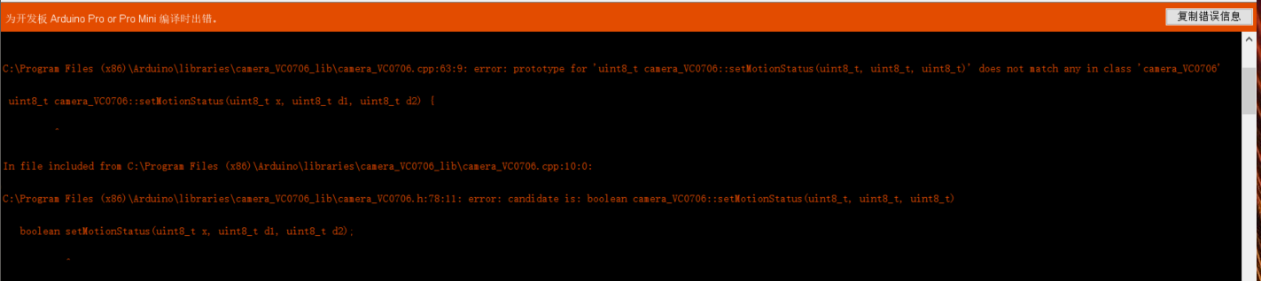
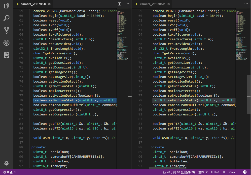
Basically, it means the function in cpp file doesn't match the declaration in the headfile. So I took a risk by changing the declaration on the function in the head file. (the code on the left is the old one) And I didn't change the code in the zip file.
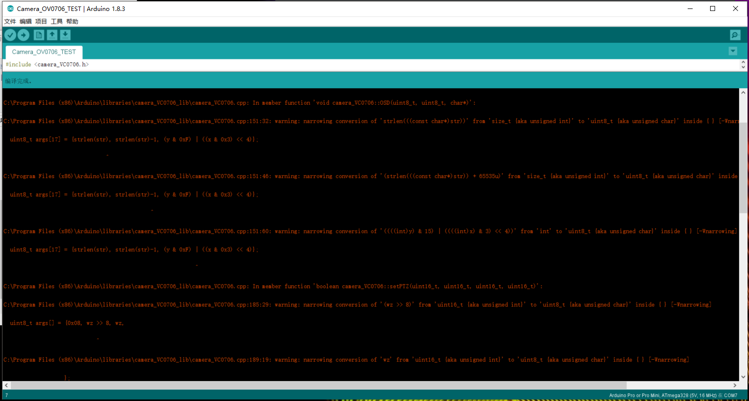
Then, the arduino IDE finished compiling with some warnings:
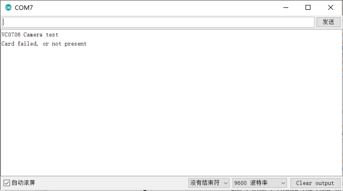
After upload the code into the shanghaino board, the serial monitor shows what was expected (the SD card shield did not arrived yet)
Day 2: error
By rechecking the guide web, a serious problem occurred: How can I connect all these pins from the ov7670 module in terms of there are only a few pins avaliable on shanghaino board? The picture on the web showed something tricky
There is only 4 pins from the camera module!
So I re-search on TaoBao, and I found this:
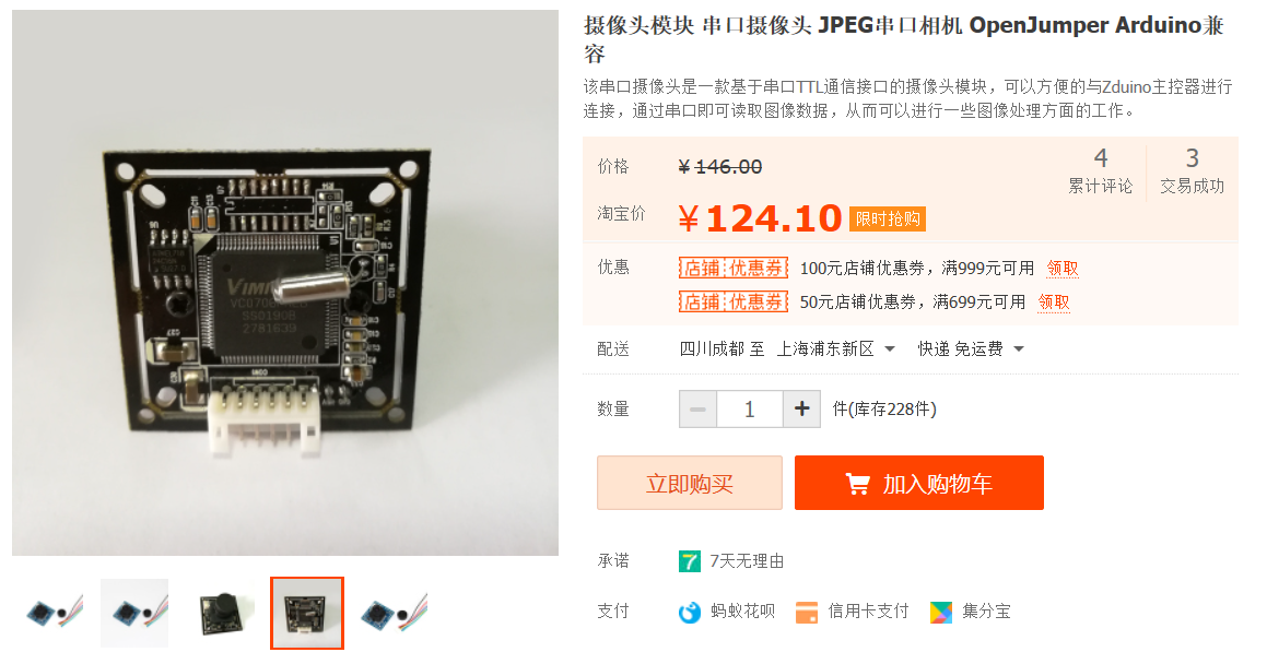
As the picture shown, there is exactly the same as the back of the camera on the website! So, I went crazy and re-buy the camera module and waiting...
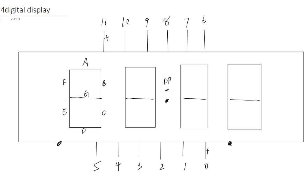
Day 3: input -> output
By waiting for the modules for shanghaino, I test some part of the compoment from the classroom. I found the 4 digits segment display, but I couldn't find the data sheet for it. So, I test it on my own. And the diagram for the display is as follows:
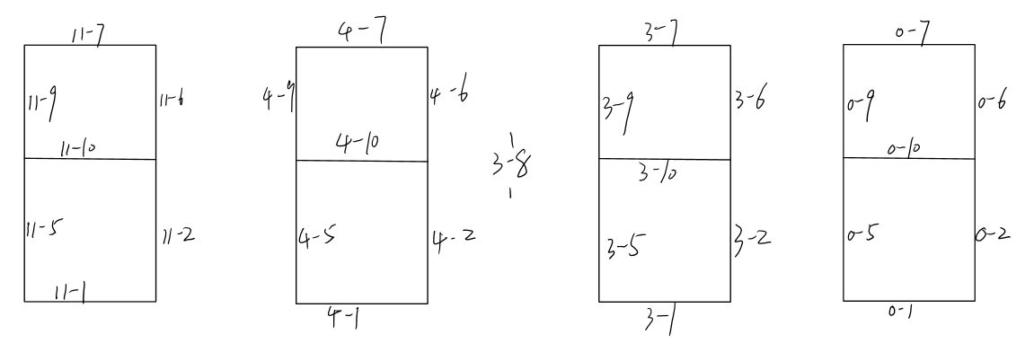
And here is the table for controlling the display. But the only way to show all 4 digits is to refresh the number one by one.
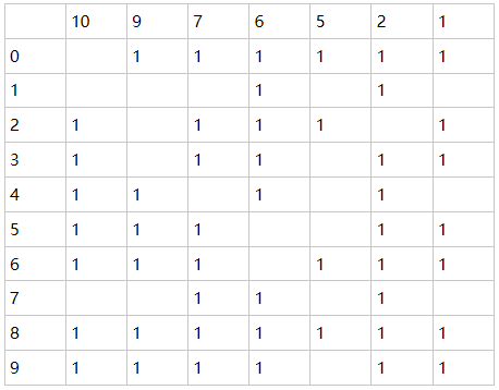
Then, I wrote a library for the controll of the display, which you can download and put it in the arduino IDE. But I will not update it further.
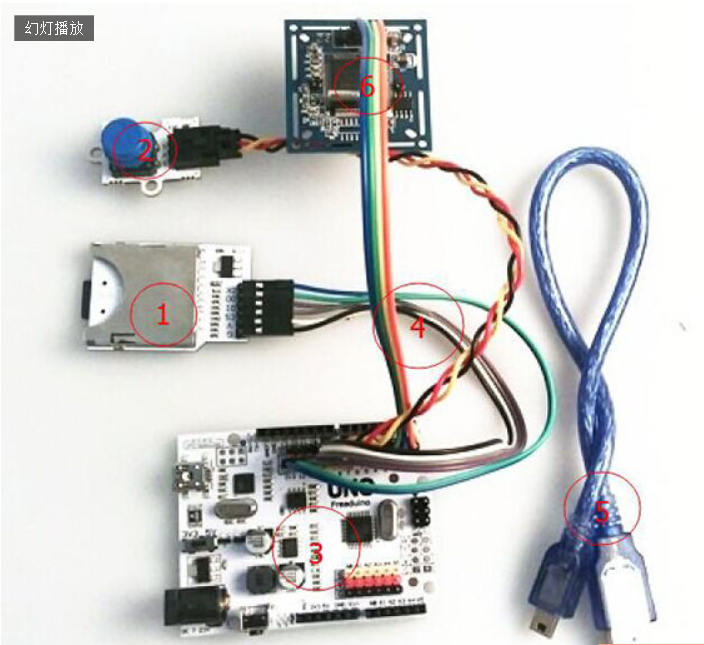
Day 4: finished circuit
Finally, I got all the necessary components I need which are:
- Arduino mini pro board
- The ov_0706 camera module
- The SD card shield
- The ultrasonic sensor
Then, I can start testing the structure
By found the graph online and modified the connection as I need, the connections for the pins on all these devices are as follows: (some of the power connections are ignored)

Then everything goes well, and I wrote the code for the final product.
Maybe at the final product, I will add a feature to show the statue using a buzzer, to let the user know whether the picture was token sucessfully.
Day5: make the head band base
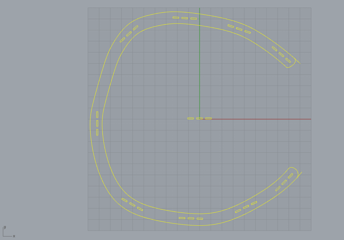
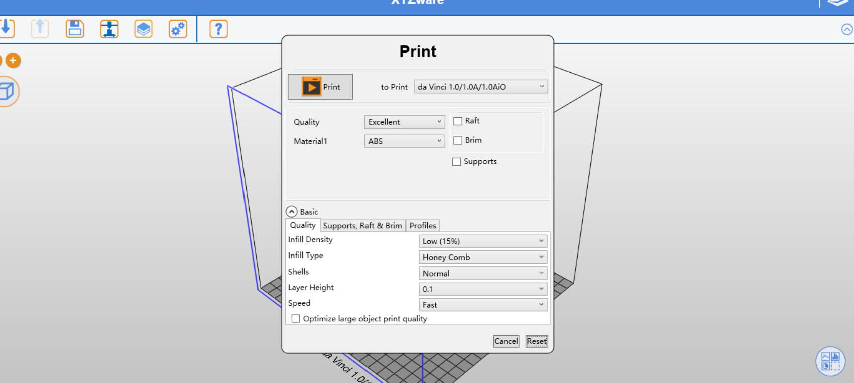
At first, I was going to print the base through the 3D printer. Luckily or unluckily, the xyz printer keeps telling me that the module I desgined was too big, and asked me kindly whether I want to transfrom it in to a smaller size... So, I decided to make the base through the laser cutter.
And this is the moduel I desgined based on the 3D module which was a scan of my head.
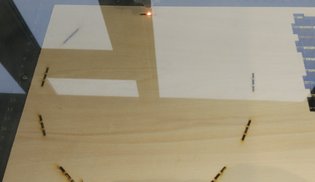
Then I set the power to 70% with 0.5 speed, to cut out the band using the laser cutter.
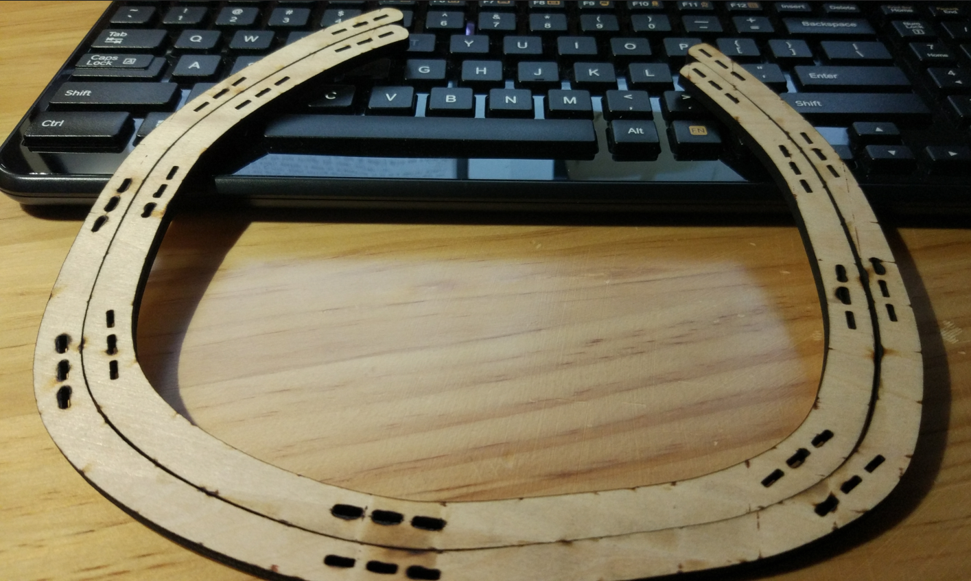
However, the initial one was a little too big to be worn on my head. Luckily again, the smaller one fit my head perfectly:)
As you can see, I desgined many joints for the components to fit in the base. Then I can 3D print the parts that holds the electric components
Day6: First joints
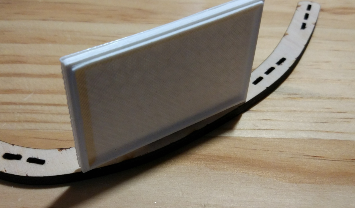
By desgining the joints which would fit into the head band base, I print the joints as well as the base holding the battery.
However, the joints are too big which toke me quite a while to make them smaller (0.5mm thinner than desgined)
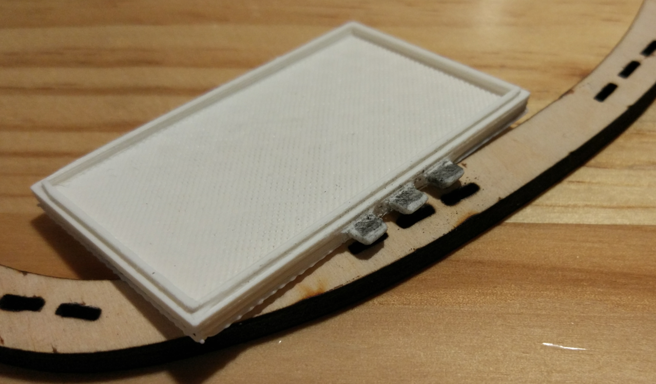
And the ideal figure of this joints with the battery base is like this:
Day 7: finished!
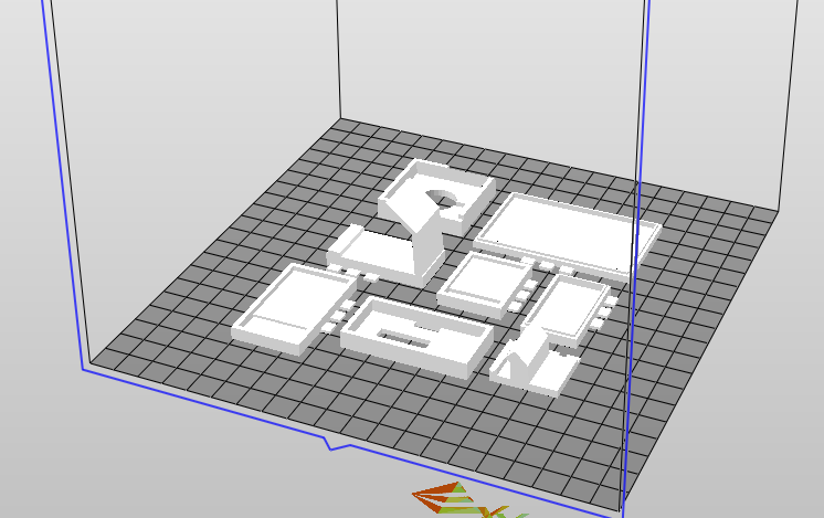
By finished testing the joints, I print all the bases at onece:
By keep solidering the wires and then install all the parts, the final products came out:
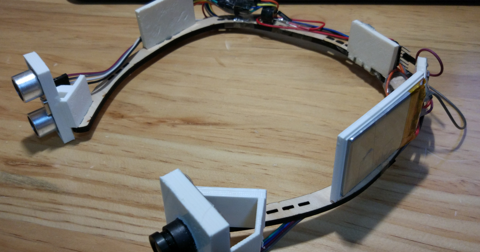
Adn last, here is the brief tutorial about how to make a head 'ring' with camera like this.